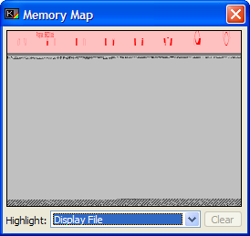
Memory Map window
The Memory Map window is available from the View menu.

This window displays a simple visual representation of the contents of the emulated Spectrum's writeable memory (RAM): addresses 16384 to 65535 inclusive. For more information, see Chapter 24.
Each pixel in the map represents one byte of memory. Shaded pixels represent non-zero values (the darker the shading, the more bits are set in the byte); blank pixels represent zero. Large blank areas generally correspond to memory that is not being used.
Highlight
Specifies which area of memory should be highlighted in red.
None |
No highlighting. |
Display file |
Highlights the area of memory where the display is kept. This does not include the Attributes region - just the raw bitmap of the display, which consists of 6,144 bytes. (See The .scr file format.) |
Attributes |
The attributes area contains the colours used to make up the display file. This can best be described as a transparent "overlay" which sits on top of the display, and is 768 bytes long. |
Printer buffer |
The printer buffer is used by the ZX printer accessory as a holding region for data that is being sent to the printer. It is also used by some programs as a temporary, but well protected area in which you can store small machine code routines. It is 256 bytes in size. |
System variables |
The System variables occupy 186 bytes, and contain flags and information used by the ROM to handle the BASIC and some other functions such as timekeeping and the display - the PRINT locations, and the coordinates last used by PLOT and DRAW, for example. These variables are discussed in more detail in Chapter 25 of the Spectrum Manual found elsewhere in this help file. |
Channels |
The channels area of memory contains a list of any channels opened by BASIC to either the screen, the keyboard, the printer, or other I/O devices. The channels region usually occupies only 34 bytes, but this can be extended by moving the PROG system variable to point higher up in memory, which will relocate your BASIC program. |
BASIC program |
This is the region of memory occupied by your program, after it has been tokenised and stored by the ROM. This area changes in size quite readily, as you edit your program. |
Variables |
The variables area begins at the address specified in the VARS system variable, and extends to incorporate all the variables used by your program. |
Edit line |
The Edit Line region of memory stores the user's keystrokes in an INPUT command. This region of memory is also used by the ROM when the user edits a line on the original hardware, but BasinC has removed this necessity by replacing the ROM editor with a newer editor. |
Workspace |
The workspace is a temporary holding area used for various operations like shuffling variables in expressions around, and other such things. |
Calculator stack |
The Calculator Stack is where the internal calculator stores it's decoded expressions and performs calculations as part of the ROM calculator. |
Spare RAM |
The Spare RAM is the (usually empty) space between the Machine stack and the calculator stack. As the Machine stack grows (due to heavy recursion or calculation) it will gradually fill this RAM from top to bottom. As it then recovers RAM and "shrinks", it will not clear the RAM as it goes. You can use the Clear button to do this - it's purely cosmetic. Note: Use this button with care - if you have machine code or data stored below RAMTOP, you will lose it. Always issue a CLEAR to reserve space for your important memory areas. |
Machine stack |
This is the region of memory pointed to by the Z80 Register SP. Note that this is likely to grow downward from RAMTOP, and as such any sensitive data stored in memory should not be stored lower than this. |
GO SUB stack |
The GO SUB stack stores line and statement numbers used as return addresses for subroutines in BASIC. It can get very large very quickly especially when a subroutine calls itself recursively. |
UDGs |
The UDGs are a list of 21 "characters" which are available to the user, for the purpose of creating your own graphics or symbols to be used in BASIC programs. For more on their use, see Chapter 14 of the Sinclair BASIC Manual, and also under the documentation of the UDG/CHARSET Editor Window. This region is normally 168 bytes in size, but altering the UDG system variable can change that. |